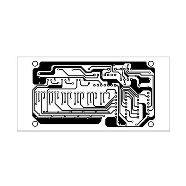
Seven-Colour RGB LED Lighting PCB Layout Design with DC5V Power Supply
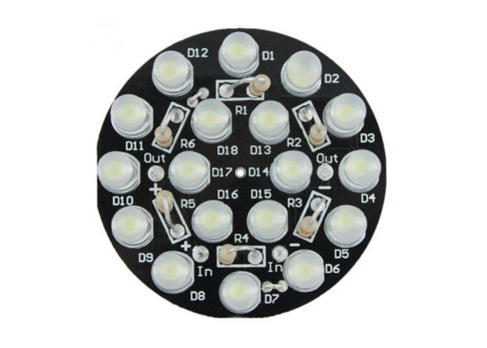
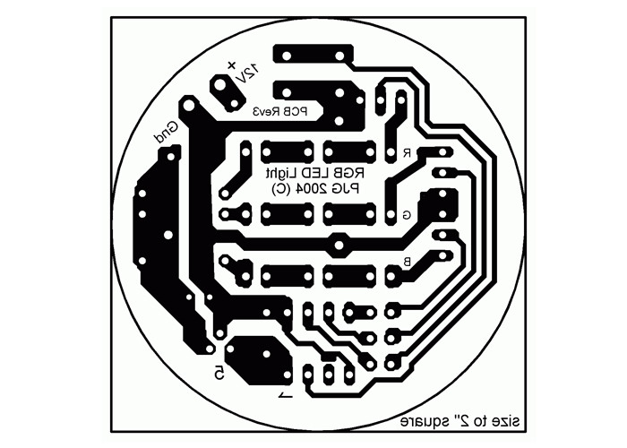
Presented here is a simple circuit that uses six red, green and blue (RGB) LEDs to generate a running-light effect in seven colours—blue, green, red, cyan, yellow, magenta and white. The RGB LEDs have four pins, one for each colour and a common cathode. Different colours can be produced by mixing the primary colours (i.e., red, green and blue).
circuit and working
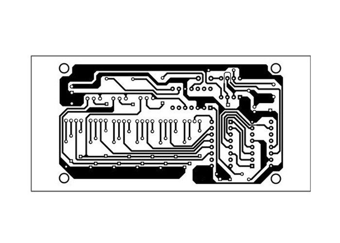
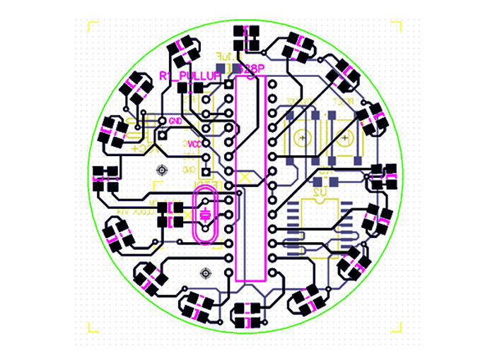
The circuit diagram for the seven-colour LED lighting is shown in Fig. 2. The circuit is built around timer NE555 (IC1), decade counter CD4017B (IC2), four-bit binary counter 7493 (IC3), driver IC ULN2003 (IC4), six RGB LEDs (RGB1 through RGB6), three BC547 transistors (T1 through T3) along with some basic components.
The timer IC NE555 (IC1) is wired in astable multivibrator mode. It provides low-frequency clock pulses, the frequency of which is decided by timing components R1, VR1 and C2. The frequency of the timer can be varied using the preset VR1.
The output of IC1 at pin 3 is fed to decade counter CD4017B (IC2). IC2 has ten outputs, which go high in sequence when a source of pulses is connected to its CLK input (pin 14). Q0 through Q5 of IC2 are connected to IN1 through IN6 of IC4. Pin Q6 of IC2 is connected back to its reset pin 15 and input pin 1 of IC3 via diode D1. When Q6 pin of IC2 goes high, it resets IC2 and, at the same time, provides the high input clock to IC3 each time after the sixth clock of IC1.
IC3 is a four-bit binary counter, and its outputs QB through QD are connected to the bases of transistors T1 through T3 via resistors R21 through R23, respectively. The binary outputs of IC3 make corresponding transistors conduct and select a different colour after each cycle (see Table I).
The common-cathode pins of each RGB LED are connected to the outputs of IC4 as shown in Fig. 2. ULN2003 is used for driving these LEDs. You can add even more RGB LEDs in parallel to the existing ones to make a larger lighting system.
The working of the circuit is simple. When the circuit is switched on, the clock pulse is generated from pin 3 of the timer IC1, making outputs of IC2 high, sequentially, which decides the switching rate of LEDs that can be changed through VR1. The colours are selected by the binary output of IC3, which changes after every sixth pulse from IC1.